
ESP32 Built-in LED Blink
- Feb 6, 2022
- 3 min read
In this article, I will tell you about my experience making the built-in LED ESP32 blinking. This project is my first ESP32 project and it was given by my lecturers. I am so excited, because this is my first hands-on on embedded project!
Prerequisites
I used Arduino IDE v1.8.19 in Windows 11 64-bit to write the code and upload the code to ESP32, you can download it in here. Just click on download, make sure it the right version and OS, and it will download a zip file. After the download is finished, extract the zip file and open the arduino.exe. It will open the IDE. You might use other IDE, but I recommend you to use Arduino IDE.
I also used some component that I bought at Jaya Plaza, electronic market located in Bandung. But you can get this component on online marketplace.
an ESP32 microcontroller
a Micro-USB type B to USB type A (Male-to-Male)
I bought the ESP32 whose legs have been soldered, I asked the guy who sold the components to solder it first. This will make it easier for future projects. But its optional, you don't have to solder the legs to make this project works.
Step 1: Open the Arduino IDE
You can open it by clicking the arduino.exe file.

Step 2: Change the additional boards manager URLs
Click Files -> Preference -> in Additional Boards Manager URLs box, add this link https://dl.espressif.com/dl/package_esp32_index.json -> then click OK button.

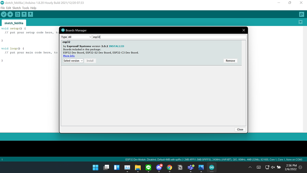
Step 3: Install ESP32 in the board manager
Click Tools -> Board -> Boards Manager -> Search for 'ESP32', after that click the Install button. The click Close button.
Step 4: Change the board to your ESP32
Click Tools -> Board -> ESP32 Arduino -> Choose your ESP32 microcontroller. I used the ESP32 Dev Module, therefore I choose the ESP32 Dev Module. Some ESP32 have the models written in their backs.

Step 5: Connect the ESP32 with your PC/laptop
Just plug in the Micro-USB type B in your ESP32 port and USB type A in your PC/Laptop port.

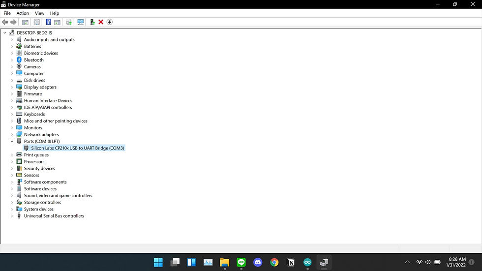
Step 6: Select the port in Arduino IDE
Click Tools -> Port -> Select whatever the port your USB shows, you can see it in Device Manager if there are so many port available. If the port in Device Manager doesn't show up, you need to install driver USB to UART bridge, you can download here.

Step 7: Write the code!
Arduino IDE give us many template code and for this project is available too. All you need to do is click File -> Examples -> 01.Basics -> Blink.

But the code isn't complete yet. You need to add your built-in LED pin number first. My built-in LED pin number is 2, so I add:
int LED_BUILTIN = 2;or
#Define LED_BUILTIN = 2;So the complete code will be:
int LED_BUILTIN = 2;
// the setup function runs once when you press reset or power the board
void setup() {
  // initialize digital pin LED_BUILTIN as an output.
  pinMode(LED_BUILTIN, OUTPUT);
}

// the loop function runs over and over again forever
void loop() {
  digitalWrite(LED_BUILTIN, HIGH);   // turn the LED on (HIGH is the voltage level)
  delay(1000);                       // wait for a second
  digitalWrite(LED_BUILTIN, LOW);    // turn the LED off by making the voltage LOW
  delay(1000);                       // wait for a second
}
You can change how fast your LED blinking by changing the delay. You can also make more blinking patterns by adding another digitalWrite HIGH and LOW with different delay.
Step 8: Upload the code to your ESP32
All you need to do is click the arrow button, then it will show the process.

If an error that says 'Failed to connect to ESP32: Time out waiting for packet header' shows up, you need to upload the code again, while uploading the code you need to press the BOOT button in your ESP32 until it says 'Done uploading'.


Step 9: LED blinking
While you upload the code to ESP32, the built-in LED will blinking. My LED color is blue, I don't know if there is any other color than that. Then it will stop after its 'Done uploading'.
This is all for my first ESP32 project. I think it is fun to hands-on this kind of things, so see you for the next one!
ps: you can use Tinkercad if you don't have the components yet + you can put your ESP32 in breadboard so it doesn't broke LOL
Comments